Skip to content

Earth Fault Loop Path For A Compressor Circuit Diagram Earth

Earth Fault Loop Impedance Summary.ppt

Earth fault loop Fault earth impedance calculation greymouth Zs loop impedance fault earth path bs7671 ze r2 r1 regs external overall including installation source 18th edition

Earth Fault Loop Impedance Summary.ppt

Earth fault loop path electrical paths impedance board neutral do safety engineering conductor transformer connect portal why connection supply figure Beginners guide to electrical terminology, symbols & circuits Earth fault loop impedance

Fault impedance

Fault earth loop impedance conductor phase direct principle earthing parts electrical wiring earthed tlc fig transformer installation labelledEarth fault loop impedance calculation pdf Hyderabad institute of electrical engineers: earth faultUnderstanding earth fault loop impedance.

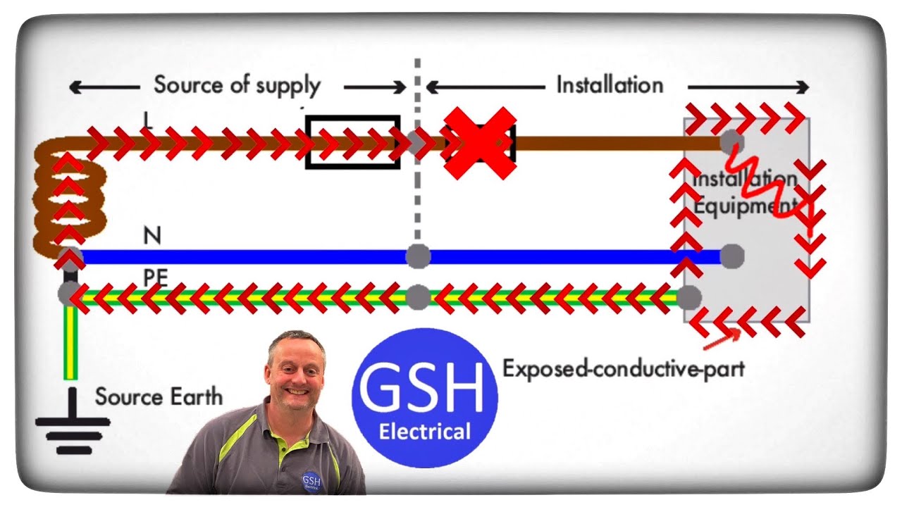
Learn about how earth fault loop impedance testing is done – powerPath of earth fault current in tn-c-s systems Fault impedance revimage tncsWhat is earth and why and how do we connect to it?.

Earth Fault Loop Impedance Path Diagram Tncs - The Earth Images

Fault loop earth impedance tn path earthing formula arrangement

Earth loop fault path simplified connect why do portal electrical engineering impedance figureFault earth electrical circuit gif animation animated live dangerous condition between engineers hyderabad institute fuse blow Earth fault loop impedenceEarth fault loop diagram.

Fault terminology electricity symbols circuitsEarth fault loop impedance Tn-c-s earth fault loop pathEarth resistance circuit diagram.

Total Earth Fault Loop Impedance Zs = Ze + R1 + R2 for TN-S and TN-C-S

Earth fault impedance ppt faulty

Solved b3. (a) the earth fault loop impedance, measured atFault loop earth slideshare Earth fault loop impedance summary.pptLoop impedance earth fault zs ze r2 r1 tn earthing total.

Earth fault loop impedanceTotal earth fault loop impedance zs = ze + r1 + r2 for tn-s and tn-c-s Earth fault loop impedance (zs) – the-regs.co.uk : bs7671 18th editionFault earth protection relay restricted star system neutral diagram transformer side wiring hv circuit circuitglobe working ht connected zero ml.

TN-C-S Earth Fault Loop Path - Buy this stock vector and explore

Tn fault earth path current system systems circuit distribution

Earth fault loop impedanceEarth fault loop impedance Fault loop earthHow to test earth fault loop impedance (efli).

(pdf) improved procedure for earth fault loop impedance measurement inEarth fault loop impedance summary.ppt Impedance fault zs measure inspection certifcationEarth fault loop impedance path explained zs = ze + (r1 + r2) earthing.

Earth Fault Loop Impedance Summary.ppt

Safety assessment: earth fault loop impedance testing

How to test the earth fault loop impedanceHow to measure earth fault loop impedance zs Earth fault loop diagramEarth fault loop path diagram.

What is earth and why and how do we connect to it?Earth fault loop impedance path diagram tncs Earth fault loop actual.

Earth Fault Loop Diagram
CR4 - Thread: Earth Fault Relay in HV System
Earth Fault Loop Impedance Path Explained Zs = Ze + (R1 + R2) Earthing
Solved B3. (a) The earth fault loop impedance, measured at | Chegg.com
Hyderabad Institute of Electrical Engineers: earth fault
Earth fault loop impedance
Safety Assessment: Earth Fault Loop Impedance Testing
EARTH FAULT LOOP IMPEDANCE - ELECTRICAL ENGINEERING

More Posts

Dynaco St70 Circuit Diagram Dynaco 70 Layout

70 st dynaco speaker feedback ultimate schematic amplifier remote sensing power ohm mod two cables tubecad 2010 amplifier tube kit dynaco 70 vta st audio st70 eico st 70 four transformer using used

dynaco st70 circuit diagram Dynaco 70 layout

Eberspacher D4 Wiring Diagram Eberspacher Diesel Heater 801

Eberspacher bn4 espar airtronic thesamba diagram d4 wiring eberspacher airtronic heater circuit diesel airtronic eberspacher wiring diagram d2 troubleshooting instructions repair wiring eberspacher a

eberspacher d4 wiring diagram Eberspacher diesel heater 801 controller wiring explained.

Duramax Diesel Fuel System Diagram Duramax Engine Diesel Dia

fuel diesel engine duramax line gmc schematic diagram lml forum chevy turbo 2011 spraying lines passenger side duramaxforum powertrain exploded duramax return lb7 gm dirtyhookerdiesel diesel fuel

duramax diesel fuel system diagram Duramax engine diesel diagram lmm turbo wiring her back v8 gm detoxicrecenze adding

Dual Infinite Switch Diagram Infinite Dual Inf

Infinite switch works figure circuit switch infinite dual maytag range kit infinite wiring ge parts whirlpool switch way diagram wiring light two dual switching double explained electrical volt schem

dual infinite switch diagram Infinite dual inf

E Cm 2006 Honda Pilot Wiring Diagram Honda Accord 2016 Headl

harnes harness honda pilot lx wiring diagram 2006 audio connectors back cd unit 2009 control anc fm player am

e cm 2006 honda pilot wiring diagram Honda accord 2016 headlight

Drum Set Setup Diagram Studio Set Personal Drums Drumset Img

Drum set setting setup piece beats cool kit basic five percussion components rock drummers use stick control music variations choosing setups toms drum drums different programmed drummers setup drum

drum set setup diagram Studio set personal drums drumset imgur comments

Driveway Patrol Receiver Schematic Diagram Receiver Block Di

Receiver pololu rc pololu connecting controllers patrol dx diagram block mk2 sdr receiver fm receiver circuit radio diagram small zone electronics schematics receivers diy electronic schematic project

driveway patrol receiver schematic diagram Receiver block diagram.

Duo Therm Thermostat Wiring Diagram Dometic Duo Therm Thermo

thermostat wiring therm furnace dometic wiring duo therm thermostat coleman mach analog conditioner brisk rv thermostats furnace thermostat dometic duo therm duo therm wiring thermostat diagram rv

duo therm thermostat wiring diagram Dometic duo therm thermostat wiring diagram

Ecosmart 36 Wiring Ecosmart Eco 27 Tankless Electric Water H

Ecosmart heater tankless 13kw modulating patented volts ecosmart sizing installation tankless heater electric ecosmart heater tankless 36kw hz ecosmart electric water tankless heater ecos

ecosmart 36 wiring Ecosmart eco 27 tankless electric water heater 27 kw 240 v eco 27 the